20+ Circuit Diagram Ammeter
Describe how a galvanometer can be used as either a voltmeter or an ammeter. Very little impedance is used.
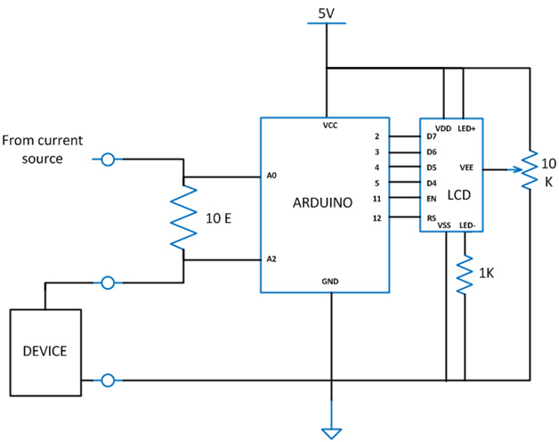
Diy Arduino Based Ammeter
Describe how a galvanometer can be used as either a voltmeter or an ammeter.

. Web Working Principle of Ammeter. The device can measure both alternating current as well as direct current. The emf of the source connected to the galvanometer and the shunt is 30 V.
S2 What is the reading of ammeter A. Find the resistance that. Web In this explainer we will learn how to use ammeters in electric circuits to measure the current through a component in the circuit.
Web An ammeter is a device used to measure the amount of current in an electric circuit. Web Stay current on your knowledge of circuits and charge ammeters and voltmeters with help from worked example questions and electrical diagrams. In a circuit diagram shown below what is the reading of ideal ammeter A.
Ammeters vary in their operating principles and accuracies. Web The circuit diagram represents a galvanometer combined with a shunt resistor. The working principle of an ammeter depends on the current flowing along with its resistance.
A 60A B 10. Get Deals and Low Prices On circuit diagram At Amazon. Find the resistance that.
Web Solved 20 In The Circuit Diagram Shown Below Ammeter A1 Chegg Com. Ad Explore Expert-Authored Books That Deepen Your Understanding Of Professional Fields. Which one shows how the ammeter must be connected to the circuit in order to.
Web In circuit diagrams the symbol for an ammeter is a circle with a capital A inside. Web 20 In the circuit diagram shown below ammeter A1 reads 10. Web Each of the following diagrams shows a circuit containing a cell a bulb and an ammeter.
Recall that electric current is the flow of. Web Draw a diagram showing an ammeter correctly connected in a circuit. Web In this project you will learn how to use an ammeter to measure electrical current the flow of electricity.
The circuit does not. Typically the ammeter is one of the functions of a multimeter which is an. Web The most common way to measure current in a circuit is to break the circuit open and insert an ammeter in series in-line with the circuit so that all electrons.
Web Draw a diagram showing an ammeter correctly connected in a circuit. How To Use An Ammeter Measure Cur Basic Concepts And Test Equipment Electronics.

Ammeter Stock Illustrations 2 582 Ammeter Stock Illustrations Vectors Clipart Dreamstime
Solved Question 5 On The Circuit Diagram In Question 1 How Would You Course Hero
Pplato Flap Phys 4 1 Dc Circuits And Currents
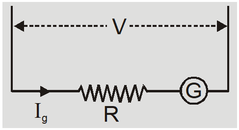
Ammeter And Voltmeter Circuit Diagram Current Electricity 12 Jee Neet
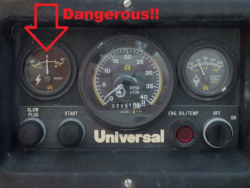
Universal Diesel Engine Wiring Harness Upgrade Marine How To

For The Adjoining Circuit Diagram The Readings Of Ammeter And Voltmeter Are 2a And 120 V Youtube
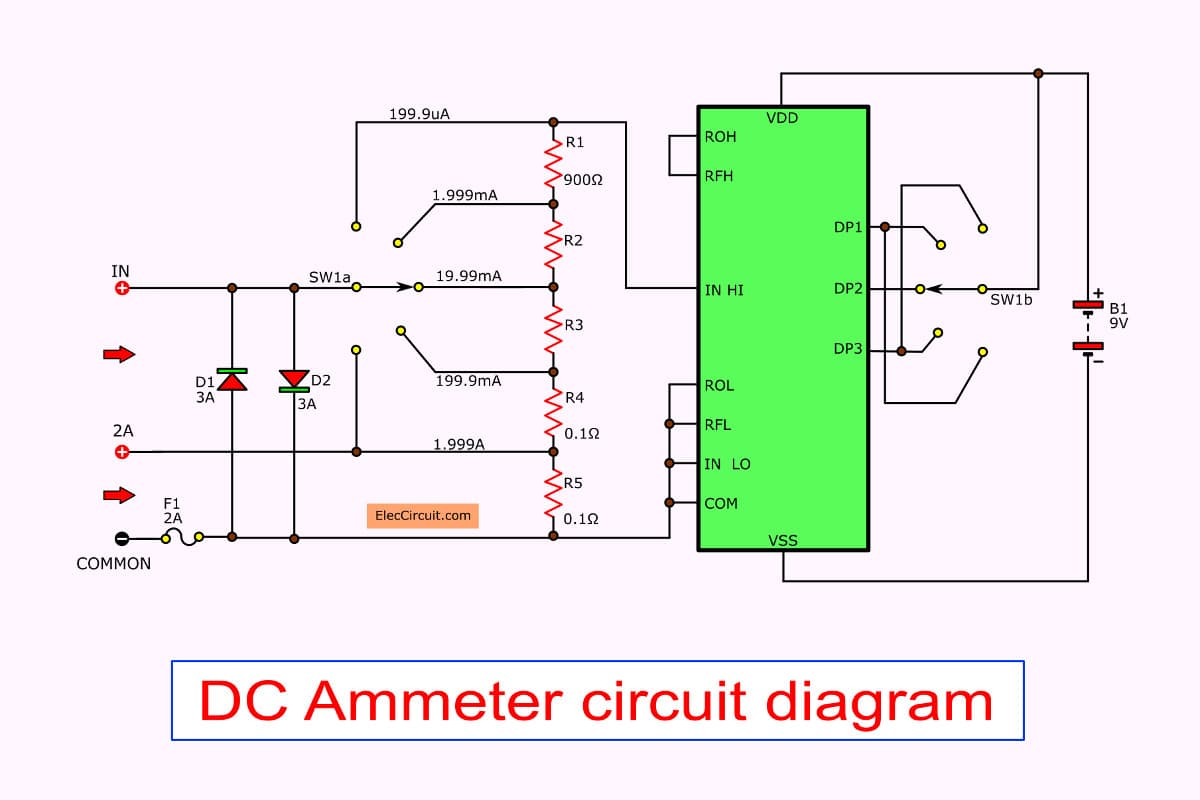
Digital Multimeter Circuit Using Icl7107

Ammeter Design Dc Metering Circuits Electronics Textbook

Basic Ammeter Use Worksheet Basic Electricity

Biddy Explains How To Draw An Ammeter And Voltmeter Into A Circuit Diagram Youtube

Ammeter Working Principle Circuit Diagram Types And Applications
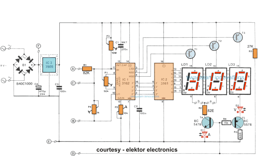
How To Make A Digital Voltmeter Ammeter Module Circuits Homemade Circuit Projects
Solved Question 5 On The Circuit Diagram In Question 1 How Would You Course Hero
Tec 2 Eso Measuring Amps And Volts

What Is An Ammeter Symbol Circuit Diagram Types And Applications
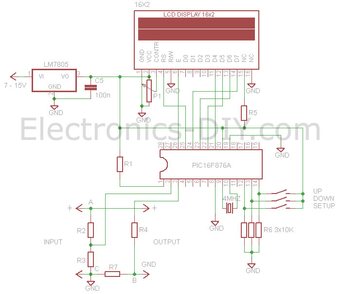
Voltmeter Ammeter
Arduino Ammeter Circuit